Switchboards for extraction systems "turnkey" according to individual customer requirements. For outputs from 1.5kW to 55kW.
The switchboards are made according to the standards valid in the EU. Country of origin: SK
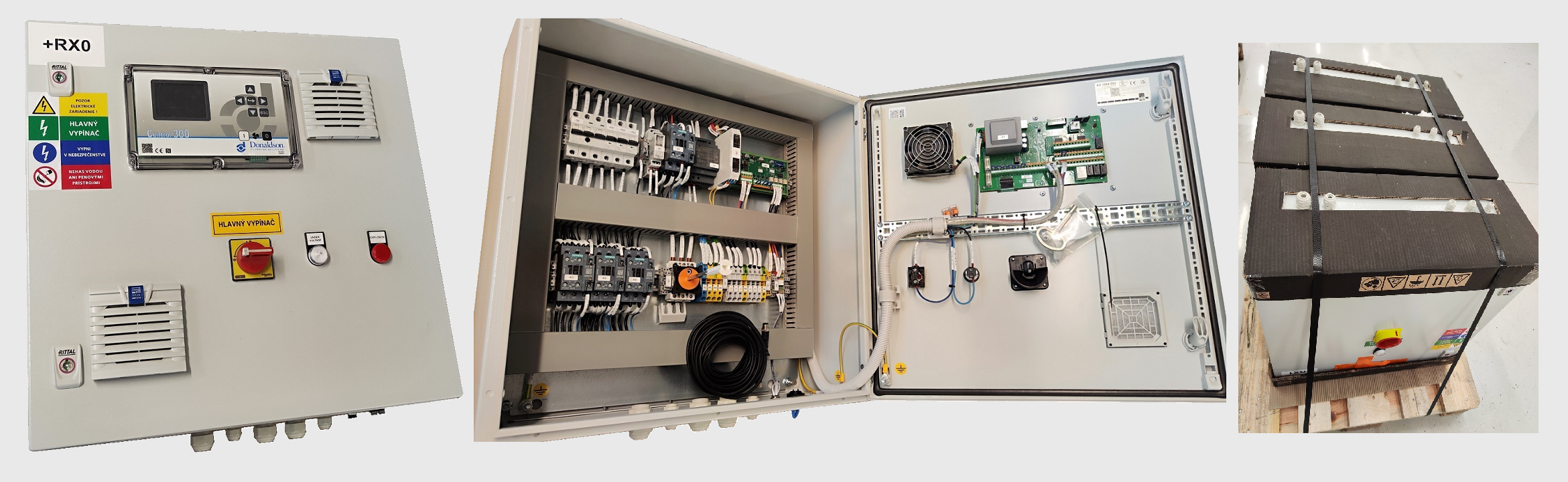
Picture-scheme
Basic configuration:
1- 400V/50Hz extraction fan electric motor power supply
2- Feedback signal from the PTC sensor from the electric motor of the exhaust fan
3- Power supply of the filter device control panel 240V/50Hz
4- 24V "ALARM" feedback signal from the filter device controller + LED indication on the PowerBox
Equipment: Switchboard design for "Outside Zone" location, Rittal cabinet or alternative, ventilation grill and fan for cooling the cabinet, frequency converter according to the power of the electric motor of the exhaust fan, cable glands below (Standard), Wiring diagram in ENG, Declaration of conformity in ENG
Mounted on the door: red-yellow main switch with the "CENTRAL STOP" function, LED indicating the "POWER" status, ON/OFF start switch for the fan, LED indication "ALARM" from the controller of the filter device
Not included: connecting cabling of components of the extraction system, Controller of filtration unit
Additional equipment:
5- Powering the electric motor of the rotary valve + "STOP" service switch
a. Additional timers for intermittent valve operation
b. For continuous operation, without timers
6- Supplying the sub-distributor of the sorbent dispenser
a. Additional timers for direct power supply and intermittent operation of the electric motors of the dispenser
b. No timers, only 240V/50Hz sub-switchboard power supply
7- Return signal "EXPLOSION" from the explosion protection switchboard, resp. from the explosive panel, etc.
8- External start of the fan by the operator
9- Outputs from the frequency converter (Modbus), e.g. error messages
10- Powering the servomotors on the closing flaps of individual duct lines for reducing suction power according to the number of simultaneously open duct lines + input signals from position sensors + LED indication of open duct lines on the panel + PLC + software + configuration of suction power
11- Powering the servo motor on the "WINTER/SUMMER" flap for the desired outlet of filtered air
Contact sales
Fill in the form below and we'll get in touch with you